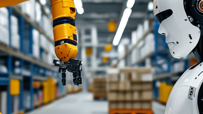
Choosing the right fanuc robot begins with the factory, not the product catalogue. Every production line has different pressures, including payload, reach, cycle time, floor space, and operator access. A six-axis model may suit welding, while a delta robot may handle lightweight packaging faster. The most expensive option is not always the most productive one.
A reliable selection process starts with measurable facts. Record the workpiece weight, gripping method, required accuracy, and hourly output. Check the robot’s reach around fixtures, conveyors, safety fencing, and maintenance areas. A small clearance mistake can force costly layout changes later. FANUC technical documentation can confirm payload curves, mounting options, controller compatibility, and programming features. An experienced integrator should also test the proposed robot with real parts, not only digital models.
No selection method is perfect. Factory conditions change. Products change faster than expected. That is why future capacity deserves attention, but excessive oversizing can waste energy, space, and budget. Consider installation support, spare-part availability, training, and recovery procedures after a fault. These details often decide whether automation feels dependable on a Monday morning.
The best fanuc robot is the one that matches the complete application. It must perform consistently, remain serviceable, and support safe daily work. A thoughtful comparison of models can reduce commissioning delays and protect long-term output. Careful questions now prevent expensive assumptions later.
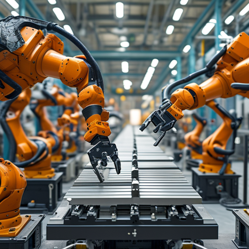
Before choosing an industrial robot, define what your factory must improve. Is the priority faster cycle times, fewer handling errors, safer material movement, or reduced operator fatigue? Measure the current process for several shifts. Record cycle time, payload, reach, product dimensions, and daily operating hours. A first estimate is often wrong. Real production data reveals hidden delays.
Operating conditions matter just as much. Check floor space, mounting position, temperature, dust, moisture, vibration, and cleaning routines. A robot near a washdown area needs suitable protection. A small workspace may require a compact arm or a different installation angle. Confirm the total payload, including grippers, cables, and workpieces. Leave enough reach and clearance for maintenance access. Safety planning should follow applicable local requirements and include guarding, emergency stops, and risk assessment.
Tips: Write the target cycle time in seconds. Test the heaviest product first. Photograph the proposed work area. Ask maintenance staff about recurring failures. Simulate awkward product positions before final selection. Avoid choosing only by maximum payload. That number can mislead. Review your assumptions with an experienced automation engineer, then run a small proof-of-concept. It may expose problems that a specification sheet cannot show.
How to Choose the Right Industrial Robot for Your Factory?
Match Robot Payload and Reach to Your Production Requirements
Choosing a robot begins with the real load, not the product label. Add the gripper, cables, tooling, and workpiece to the payload calculation. A six-kilogram part may require a twelve-kilogram robot after tooling is installed. Keep a safety margin for acceleration and unexpected movement.
Reach must fit the entire work envelope. Measure the distance from the mounting base to the farthest pick, weld, or placement point. Check the wrist angle at each position, especially near corners. A robot can reach a target but still lack useful motion. That difference often causes costly layout changes. Leave space for guarding and maintenance access.
Production speed also changes the selection. High cycle rates increase acceleration forces and may reduce practical payload. Review duty cycles, repeatability data, and the manufacturer’s load charts with a qualified integrator. I once saw a line designed around maximum reach, while most tasks sat close to the base. The chosen arm was larger, slower, and more expensive than necessary. That decision looked reasonable on paper. It was not. Test the complete tool and part together before approval, because estimates can hide vibration, cable drag, or awkward wrist loading.
| Robot Application Class | Typical Total Payload | Recommended Payload Rating | Typical Horizontal Reach | Typical Cycle or Motion Profile | Suitable Production Requirements | Key Selection Considerations |
|---|---|---|---|---|---|---|
| Small Part Assembly | 1–3 kg | 3–5 kg | 400–700 mm | High-frequency, precise positioning | Electronic components, small plastic parts, light fastening, inspection handling | Prioritize repeatability, compact installation space, cable routing, and wrist inertia limits. |
| Machine Tending | 5–15 kg | 10–20 kg | 700–1,300 mm | Repeated load-in and load-out cycles | CNC loading, press tending, injection molding, part transfer between fixtures | Include the workpiece, gripper, brackets, sensors, and any workholding accessories in the payload calculation. |
| Packaging and Case Packing | 8–25 kg | 15–35 kg | 1,000–2,000 mm | Fast pick-and-place with frequent acceleration | Carton loading, tray packing, product sorting, secondary packaging | Check wrist moment, acceleration limits, gripper jaw capacity, and the required access to the full packing area. |
| Palletizing | 15–45 kg | 25–60 kg | 1,500–3,200 mm | Repeated stacking across a large envelope | Boxes, sacks, containers, finished-goods pallet formation | Confirm the maximum pallet height, pattern size, conveyor position, tool offset, and payload at the most extended position. |
| Heavy Material Handling | 50–120 kg | 70–150 kg | 2,000–3,500 mm | Controlled transfer with moderate acceleration | Metal components, engine parts, heavy castings, large containers | Evaluate floor loading, foundation stiffness, stopping distance, tool inertia, and safety-rated operating zones. |
| Welding and Process Operations | 5–20 kg | 10–25 kg | 1,000–2,000 mm | Continuous path motion and stable orientation | Arc welding, dispensing, cutting, sealing, surface treatment | Allow payload capacity for the process torch, hose package, dress pack, sensors, and required wrist orientation. |
| Large-Workpiece Processing | 20–80 kg | 35–100 kg | 1,800–3,000 mm | Long-reach positioning with stable tool control | Grinding, deburring, sealing, drilling, handling large fabricated parts | Select based on stiffness and reach at the tool center point, not only the robot's maximum advertised reach. |
| Compact Collaborative Workcell | 2–10 kg | 5–12 kg | 700–1,300 mm | Human-shared operation with controlled speed | Light assembly, kitting, inspection, small-part loading, ergonomic assistance | Payload suitability does not by itself determine safe collaborative operation; complete risk assessment and safeguarding are required. |
| Multi-Robot Line Transfer | 10–40 kg | 20–50 kg | 1,200–2,500 mm | Coordinated transfer between conveyors or stations | Assembly-line transfer, synchronized loading, inspection handoff, production buffering | Check reach overlap, interference zones, conveyor timing, singularities, and the robot's ability to maintain the required cycle time. |
Start with the motion, not the robot model. A six-axis articulated robot suits irregular assembly, welding, and frequent tool changes. A delta robot handles rapid pick-and-place tasks over short, repeatable paths. SCARA systems fit horizontal assembly, insertion, and light packaging. Cartesian robots remain practical for straight-line handling and basic machine tending.
Match each robot type to payload, reach, cycle time, accuracy, washdown exposure, and operator access. The International Federation of Robotics recorded 541,302 industrial robot installations worldwide in 2023 (World Robotics 2024). That growth does not justify choosing the fastest arm. A high-speed delta robot may struggle when products vary or vision latency increases. A six-axis robot may run slower, yet provide greater flexibility. Measure the real cycle.
Use the actual gripper, fixture, product, and safety layout during trials. Deloitte’s 2024 Smart Manufacturing Survey found that 86% of manufacturers viewed smart manufacturing as a major competitiveness driver. However, integration costs can weaken an otherwise attractive return. Maintenance teams should review cable routing, spare-part access, programming effort, and recovery procedures. A spreadsheet can mislead. Record rejected parts, stoppages, and changeover minutes during a pilot. I would also challenge optimistic supplier estimates. Real factories contain dust, uneven products, rushed operators, and imperfect data. The best robot type is the one that performs reliably under those conditions.
Select the best robot type for each manufacturing task by comparing typical payload capacity and application requirements.
Typical payload ranges vary by model and configuration. Delta robots are suited to high-speed picking and sorting, SCARA robots to fast assembly and small-part handling, articulated robots to welding and machine tending, collaborative robots to flexible low-volume work, and heavy-payload articulated robots to palletizing and large-part handling. Always verify reach, wrist inertia, cycle time, accuracy, safety requirements, and end-of-arm tooling before making a final selection.
Choosing the right factory robot starts with the task, not the catalog. Measure cycle time, payload, reach, and wrist movement at the actual workstation. A faster robot is not always better. Excess speed can increase vibration, product damage, and maintenance demands. In one packaging line, reducing acceleration improved placement consistency more than raising maximum speed.
Accuracy also needs practical testing. Check repeatability with the real gripper, fixture, and product weight. Small positioning errors can become expensive when holes, seals, or connectors must align repeatedly. Ask for performance data under heat, dust, and extended shifts. Laboratory figures may not reflect production conditions. Measure twice.
Safety should be designed into the cell, not added after installation. Use guarding, scanners, safe-speed functions, and clear access points based on a documented risk assessment. Operators need visible status signals and simple recovery procedures. A complex safety interface may be technically strong but difficult during a rushed changeover. Keep people visible. Train maintenance staff with realistic fault scenarios, not only classroom examples.
Integration determines whether the robot becomes useful quickly. Confirm compatibility with the controller, conveyor, vision system, sensors, and factory network. Standard communication protocols can reduce custom programming, but they do not eliminate commissioning work. Leave time for signal testing and fault handling. I have seen integration plans overlook manual mode, creating delays during product changes. Review the full workflow with operators before purchase.
Choosing a robot starts with the installation area, not the catalog. Measure floor space, reach, payload, guarding, and cable routes. Check the floor rating before delivery. A heavy unit may need reinforcement. Leave access for technicians and safe operator movement. Small clearances create large service problems.
Programming needs equal attention. Confirm whether your team can create, test, and modify programs locally. Ask for offline simulation, clear error messages, and training suited to actual tasks. Record cycle time using the real tool, workpiece, and motion path. A quoted cycle time can look impressive. It may fail under production conditions. Test it.
Maintenance planning should be practical. Identify lubrication points, inspection intervals, spare components, and backup procedures. Keep program versions and calibration records in a controlled location. Train at least two employees, because one expert can become a bottleneck. Review electrical connections, end-of-arm tooling, and safety circuits regularly.
Plan future expansion now. Reserve network capacity, floor space, and controller inputs for another station. Still, avoid buying unused capacity without evidence. In practice, our early forecasts have sometimes been too optimistic. Actual demand changed after installation. A staged design can protect the budget while keeping the next upgrade possible.